Geometry.Svg
Draw 2D elm-geometry values as SVG.
A note on unit conversions
Since plain Svg values do not track what units or coordinate systems were used
to create them (unlike elm-geometry values such as Point2ds, Rectangle2ds
etc.), you lose some type safety when using the functions in this package to
convert from elm-geometry values to SVG. For example, the following doesn't
make sense (since the units don't match up) but will compile just fine since
the return value of the Svg.lineSegment2d function has no way of indicating
that it's in units of meters, not pixels:
Svg.translateBy (Vector2d.pixels 300 400) <|
    Svg.lineSegment2d []
        (LineSegment.from
            (Point2d.meters 10 10)
            (Point2d.meters 20 20)
        )
Also note that because of how elm-geometry and elm-units works, something
like
Svg.lineSegment2d [] <|
    LineSegment2d.from
        (Point2d.inches 1 2)
        (Point2d.inches 3 4)
will actually create a SVG element like
<polyline points="0.0254,0.0508 0.0762,0.1016"/>since all values get converted to and stored internally as base units (meters or
pixels). You can avoid this issue by using the at or at_
functions to explicitly apply a conversion from (in this example) inches to
on-screen pixels:
let
    lineSegment =
        LineSegment2d.from
            (Point2d.inches 1 2)
            (Point2d.inches 3 4)


    resolution =
        pixels 96 |> Quantity.per (Length.inches 1)
in
Svg.at resolution (Svg.lineSegment2d [] lineSegment)
which will result in something like
<g transform="scale(3779.5276)">
    <polyline points="0.0254,0.0508 0.0762,0.1016"/>
</g>
If you want to let the compiler check whether your units make sense, you could change the above code to directly scale the line segment first and then draw it:
Svg.lineSegment2d [] <|
    LineSegment2d.at resolution lineSegment
This will result in simply
<polyline points="96,192 288,384"/>which should be visually identical to the <g> version but will let the Elm
compiler check whether the given conversion factor is valid to apply to the
given line segment. The downside to this approach is that changing the
resolution/scale factor, for example when zooming, then transforms the actual
geometry before rendering it to SVG instead of rendering the same geometry to
SVG and just changing what transformation is applied to it. For large, complex
geometry, transforming the geometry itself is likely to be expensive, while just
changing a transformation should be cheap.
Reading this documentation
For the examples, assume that the following imports are present:
import Svg exposing (Svg)
import Svg.Attributes as Attributes
import Geometry.Svg as Svg
import Angle
import Pixels exposing (pixels)
Also assume that any necessary elm-geometry modules/types have been imported
using the following format:
import Point2d exposing (Point2d)All examples use a Y-up coordinate system instead of SVG's Y-down (window)
coordinate system; they were all rendered with a final relativeTo
call to flip the example 'upside down' for display.
Geometry
These functions turn elm-geometry 2D values into SVG elements with geometric
attributes such as points and transform set appropriately. Each function
also accepts a list of additional SVG attributes such as fill or stroke that
should be added to the resulting element.
Draw a Triangle2d as an SVG <polygon> with the given attributes.

triangle : Svg msg
triangle =
    Svg.triangle2d
        [ Attributes.stroke "blue"
        , Attributes.strokeWidth "10"
        , Attributes.strokeLinejoin "round"
        , Attributes.fill "orange"
        ]
        (Triangle2d.fromVertices
            ( Point2d.pixels 100 100
            , Point2d.pixels 200 100
            , Point2d.pixels 100 200
            )
)Draw a Polyline2d as an SVG <polyline> with the given attributes.

polyline : Svg msg
polyline =
    Svg.polyline2d
        [ Attributes.stroke "blue"
        , Attributes.fill "none"
        , Attributes.strokeWidth "5"
        , Attributes.strokeLinecap "round"
        , Attributes.strokeLinejoin "round"
        ]
        (Polyline2d.fromVertices
            [ Point2d.pixels 100 100
            , Point2d.pixels 120 200
            , Point2d.pixels 140 100
            , Point2d.pixels 160 200
            , Point2d.pixels 180 100
            , Point2d.pixels 200 200
            ]
)Draw a Polygon2d as an SVG <polygon> with the given attributes.

polygon : Svg msg
polygon =
    Svg.polygon2d
        [ Attributes.stroke "blue"
        , Attributes.fill "orange"
        , Attributes.strokeWidth "3"
        ]
        (Polygon2d.withHoles
            [ [ Point2d.pixels 150 185
              , Point2d.pixels 165 160
              , Point2d.pixels 135 160
              ]
            ]
            [ Point2d.pixels 100 200
            , Point2d.pixels 120 150
            , Point2d.pixels 180 150
            , Point2d.pixels 200 200
            ]
)Draw a Rectangle2d as an SVG <rectangle> with the given attributes.
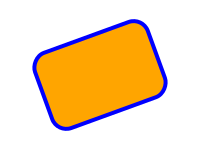
rectangle : Svg msg
rectangle =
    let
        axes =
            Frame2d.atPoint (Point2d.pixels 150 150)
                |> Frame2d.rotateBy (Angle.degrees 20)
    in
    Svg.rectangle2d
        [ Attributes.stroke "blue"
        , Attributes.fill "orange"
        , Attributes.strokeWidth "4"
        , Attributes.rx "15"
        , Attributes.ry "15"
        ]
        (Rectangle2d.centeredOn axes
            ( pixels 120, pixels 80 )
)Draw an Arc2d as an SVG <path> with the given attributes.
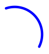
arc : Svg msg
arc =
    Svg.arc2d
        [ Attributes.stroke "blue"
        , Attributes.strokeWidth "5"
        ]
        (Point2d.pixels 150 50
            |> Arc2d.sweptAround
                (Point2d.pixels 100 100)
                (Angle.degrees 90)
)Draw an EllipticalArc2d as an SVG <path> with the given attributes.
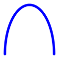
ellipticalArc : Svg msg
ellipticalArc =
    Svg.ellipticalArc2d
        [ Attributes.stroke "blue"
        , Attributes.fill "none"
        , Attributes.strokeWidth "5"
        , Attributes.strokeLinecap "round"
        ]
        (EllipticalArc2d.with
            { centerPoint = Point2d.pixels 100 10
            , xDirection = Direction2d.x
            , xRadius = pixels 50
            , yRadius = pixels 100
            , startAngle = Angle.degrees 0
            , sweptAngle = Angle.degrees 180
            }
)Draw a Circle2d as an SVG <circle> with the given attributes.

circle : Svg msg
circle =
    Svg.circle2d
        [ Attributes.fill "orange"
        , Attributes.stroke "blue"
        , Attributes.strokeWidth "2"
        ]
        (Circle2d.withRadius (pixels 10)
            (Point2d.pixels 150 150)
)Draw an Ellipse2d as an SVG <ellipse> with the given attributes.
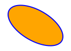
ellipse : Svg msg
ellipse =
    Svg.ellipse2d
        [ Attributes.fill "orange"
        , Attributes.stroke "blue"
        , Attributes.strokeWidth "2"
        ]
        (Ellipse2d.with
            { centerPoint = Point2d.pixels 150 150
            , xDirection = Direction2d.degrees -30
            , xRadius = pixels 60
            , yRadius = pixels 30
            }
)Draw a quadratic spline as an SVG <path> with the given attributes.
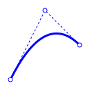
quadraticSpline : Svg msg
quadraticSpline =
    let
        firstControlPoint =
            Point2d.pixels 50 50


        secondControlPoint =
            Point2d.pixels 100 150


        thirdControlPoint =
            Point2d.pixels 150 100


        spline =
            QuadraticSpline2d.fromControlPoints
                firstControlPoint
                secondControlPoint
                thirdControlPoint


        controlPoints =
            [ firstControlPoint
            , secondControlPoint
            , thirdControlPoint
            ]


        drawPoint point =
            Svg.circle2d [] <|
                Circle2d.withRadius (pixels 3) point


    in
    Svg.g [ Attributes.stroke "blue" ]
        [ Svg.quadraticSpline2d
            [ Attributes.strokeWidth "3"
            , Attributes.strokeLinecap "round"
            , Attributes.fill "none"
            ]
            spline
        , Svg.polyline2d
            [ Attributes.strokeWidth "1"
            , Attributes.fill "none"
            , Attributes.strokeDasharray "3 3"
            ]
            (Polyline2d.fromVertices controlPoints)
        , Svg.g [ Attributes.fill "white" ]
            (List.map drawPoint controlPoints)
]Draw a cubic spline as an SVG <path> with the given attributes.
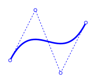
cubicSpline : Svg msg
cubicSpline =
    let
        firstControlPoint =
            Point2d.pixels 50 50


        secondControlPoint =
            Point2d.pixels 100 150


        thirdControlPoint =
            Point2d.pixels 150 25


        fourthControlPoint =
            Point2d.pixels 200 125


        spline =
            CubicSpline2d.fromControlPoints
                firstControlPoint
                secondControlPoint
                thirdControlPoint
                fourthControlPoint


        controlPoints =
            [ firstControlPoint
            , secondControlPoint
            , thirdControlPoint
            , fourthControlPoint
            ]


        drawPoint point =
            Svg.circle2d [] <|
                Circle2d.withRadius (pixels 3) point
    in
    Svg.g [ Attributes.stroke "blue" ]
        [ Svg.cubicSpline2d
            [ Attributes.strokeWidth "3"
            , Attributes.strokeLinecap "round"
            , Attributes.fill "none"
            ]
            spline
        , Svg.polyline2d
            [ Attributes.strokeWidth "1"
            , Attributes.fill "none"
            , Attributes.strokeDasharray "3 3"
            ]
            (Polyline2d.fromVertices controlPoints)
        , Svg.g [ Attributes.fill "white" ]
            (List.map drawPoint controlPoints)
]Draw a bounding box as an SVG <rect> with the given attributes.
Transformations
These functions allow you to use all the normal elm-geometry 2D transformations on
arbitrary fragments of SVG. For example,
Svg.mirrorAcross Axis2d.x
    (Svg.lineSegment2d [] lineSegment)
draws a line segment as SVG and then mirrors that SVG fragment. This is visually the same as
Svg.lineSegment2d []
    (LineSegment2d.mirrorAcross Axis2d.x lineSegment)
which instead mirrors the line segment first and then draws the mirrored line segment as SVG.
In the above example only a single SVG element was transformed, but all of these transformation functions work equally well on arbitrarily complex fragments of SVG such as nested groups of elements of different types:
Svg.rotateAround Point2d.origin
    (Angle.degrees 30)
    (Svg.g [ Attributes.stroke "blue" ]
        [ Svg.lineSegment2d [] lineSegment
        , Svg.circle2d [] someCircle
        , Svg.g [ Attributes.fill "orange" ]
            [ Svg.triangle2d [] firstTriangle
            , Svg.triangle2d [] secondTriangle
            ]
        ]
    )
If the transformation changes frequently (an animated rotation angle, for example) while the geometry itself remains constant, using an SVG transformation can be more efficient since the geometry itself does not have to be recreated (the SVG virtual DOM only has to update a transformation matrix).
Scale arbitrary SVG around a given point by a given scale.

scaled : Svg msg
scaled =
    let
        scales =
            [ 1.0, 1.5, 2.25 ]


        referencePoint =
            Point2d.pixels 100 100


        referencePoint =
            Svg.circle2d [ Attributes.fill "black" ] <|
                Circle2d.withRadius (pixels 3)
                    referencePoint


        scaledCircle : Float -> Svg msg
        scaledCircle scale =
            Svg.scaleAbout referencePoint scale circle
    in
    Svg.g []
        (referencePoint
            :: List.map scaledCircle scales
        )
Note how everything is scaled, including the stroke width of the circles. This
may or may not be what you want; if you wanted the same stroke width on all
circles, you could instead scale the Circle2d values themselves using
Circle2d.scaleAbout and then draw the scaled circles with a specific stroke
width using Svg.circle2d.
Rotate arbitrary SVG around a given point by a given angle.

rotated : Svg msg
rotated =
    let
        angles =
            Parameter1d.steps 9 <|
                Quantity.interpolateFrom
                    (Angle.degrees 0)
                    (Angle.degrees 270)


        referencePoint =
            Point2d.pixels 200 150


        referenceCircle =
            Svg.circle2d [ Attributes.fill "black" ] <|
                (Circle2d.withRadius (pixels 3)
                    referencePoint
                )


        rotatedCircle : Float -> Svg msg
        rotatedCircle angle =
            Svg.rotateAround referencePoint angle circle
    in
    Svg.g [] <|
        referenceCircle
:: List.map rotatedCircle anglesTranslate arbitrary SVG by a given displacement.

translated : Svg msg
translated =
    Svg.g []
        [ polyline
        , polyline
            |> Svg.translateBy (Vector2d.pixels 0 40)
        , polyline
            |> Svg.translateBy (Vector2d.pixels 5 -60)
]Mirror arbitrary SVG across a given axis.

mirrored : Svg msg
mirrored =
    let
        horizontalAxis =
            Axis2d.through (Point2d.pixels 0 220)
                Direction2d.x


        horizontalSegment =
            LineSegment2d.along horizontalAxis
                (pixels 50)
                (pixels 250)


        angledAxis =
            Axis2d.through (Point2d.pixels 0 150)
                (Direction2d.degrees -10)


        angledSegment =
            LineSegment2d.along angledAxis
                (pixels 50)
                (pixels 250)
    in
    Svg.g []
        [ polygon
        , Svg.mirrorAcross horizontalAxis polygon
        , Svg.mirrorAcross angledAxis polygon
        , Svg.g
            [ Attributes.strokeWidth "0.5"
            , Attributes.stroke "black"
            , Attributes.strokeDasharray "3 3"
            ]
            [ Svg.lineSegment2d [] horizontalSegment
            , Svg.lineSegment2d [] angledSegment
            ]
        ]
Unit conversions
Take some SVG that is assumed to be defined in units1 and convert it to
one defined in units2, given a conversion factor defined as units2 per
units1. This is equivalent to a multiplication by that conversion factor. For
example, you could create an SVG element in units of meters and then scale it to
a certain on-screen size:
let
    pixelsPerMeter =
        pixels 10 |> Quantity.per (Length.meters 1)
in
Svg.at pixelsPerMeter <|
    Svg.lineSegment2d [] <|
        LineSegment2d.from
            (Point2d.meters 1 2)
            (Point2d.meters 3 4)
Note that you can mix and match what specific units you use as long as the
underlying units match up. For example, something like this would work out since
both centimeters and feet both have the same underlying units (meters):
let
    onePixelPerCentimeter =
        pixels 1 |> Quantity.per (Length.centimeters 1)
in
Svg.at onePixelPerCentimeter <|
    Svg.lineSegment2d [] <|
        LineSegment2d.from
            (Point2d.feet 1 2)
            (Point2d.feet 3 4)
This will result in something like:
<g transform="scale(100)">
    <polyline points="0.3048,0.6096 0.9144,1.2192"/>
</g>
(One foot is 30.48 centimeters or 0.3048 meters.)
Similar to at, but if you have an 'inverse' rate instead. For example:
let
    metersPerPixels =
        Length.millimeters 1 |> Quantity.per (pixels 1)
in
Svg.at_ metersPerPixel <|
    Svg.lineSegment2d [] <|
        LineSegment2d.from
            (Point2d.centimeters 1 2)
            (Point2d.centimeters 3 4)
This would be equivalent to
let
    pixelsPerMeter =
        pixels 1 |> Quantity.per (Length.millimeters 1)
in
Svg.at pixelsPerMeter <|
    Svg.lineSegment2d [] <|
        LineSegment2d.from
            (Point2d.centimeters 1 2)
            (Point2d.centimeters 3 4)
Coordinate conversions
These functions allow elm-geometry coordinate conversion transformations to be
applied to arbitrary SVG elements. Note that the same caveats as unit
conversions apply: you'll have to be careful to verify yourself that the
coordinate conversions actually make sense, since the compiler will be unable to
check for you.
Convert SVG expressed in global coordinates to SVG expressed in coordinates
relative to a given reference frame. Using relativeTo can be useful for
transforming between model space and screen space - SVG coordinates start in the
top left, so positive Y is down, while in mathematical/geometric contexts
positive Y is usually up.
For example, you might develop an SVG scene in a coordinate system where X and Y each range from 0 to 300 and positive Y is up. To turn this into a 300x300 SVG drawing, first define the top-left SVG frame (coordinate system) in terms of the model coordinate system:
topLeftFrame =
    Frame2d.atPoint (Point2d.pixels 0 300)
        |> Frame2d.reverseY
(As expressed in the model frame, the top-left SVG frame is at the point
(0, 300) and its Y direction is equal to the global negative Y direction.) If
scene is an SVG element representing your scene, you could then transform it
into top-left SVG window coordinates and render the result to HTML with
Svg.svg
    [ Attributes.width "300"
    , Attributes.height "300"
    ]
    [ Svg.relativeTo topLeftFrame scene ]
Note however that if you do this, any text you added will come out upside down!
If, like me, you really prefer to use a Y-up coordinate system when drawing,
you could write a little helper function that rendered text at a particular
point and then flipped it upside down (mirrored it across a horizontal axis) so
that your final relativeTo would flip it back to right side up. Something
like:
drawText :
    List (Svg.Attribute msg)
    -> Point2d units coordinates
    -> String
    -> Svg msg
drawText givenAttributes position content =
    let
        { x, y } =
            Point2d.unwrap position


        positionAttributes =
            [ Svg.Attributes.x (String.fromFloat x)
            , Svg.Attributes.y (String.fromFloat y)
            ]
    in
    Svg.text_ (positionAttributes ++ givenAttributes)
        [ Svg.text content ]
        |> Svg.mirrorAcross
(Axis2d.through position Direction2d.x)Take SVG defined in local coordinates relative to a given reference frame, and return that SVG expressed in global coordinates.
This can be useful for taking a chunk of SVG and 'stamping' it in different positions with different orientations:

placed : Svg msg
placed =
    let
        vertices =
            [ Point2d.origin
            , Point2d.pixels 40 0
            , Point2d.pixels 50 25
            , Point2d.pixels 10 25
            ]


        stamp =
            Svg.polygon2d
                [ Attributes.fill "orange"
                , Attributes.stroke "blue"
                , Attributes.strokeWidth "2"
                ]
                (Polygon2d.singleLoop vertices)


        frames =
            [ Frame2d.atPoint (Point2d.pixels 25 25)
            , Frame2d.atPoint (Point2d.pixels 100 25)
            , Frame2d.atPoint (Point2d.pixels 175 25)
                |> Frame2d.rotateBy (Angle.degrees 20)
            , Frame2d.atPoint (Point2d.pixels 25 150)
            , Frame2d.atPoint (Point2d.pixels 100 100)
                |> Frame2d.rotateBy (Angle.degrees 20)
            , Frame2d.atPoint (Point2d.pixels 150 150)
                |> Frame2d.rotateBy (Angle.degrees -30)
            ]
    in
    Svg.g []
        (frames
            |> List.map
                (\frame -> Svg.placeIn frame stamp)
        )
Draw a
LineSegment2das an SVG<polyline>with the given attributes.